Transmission Line Protection
Distance Relays: -
Introduction:
The impedance relays also called distance relays are employed to provide protection to transmission lines connected in a network as they are economic and possess several technical advantages. They are comparatively simple to apply, operate with extremely high speed, and both primary and backup protection features are inherent in them. Moreover, they can be easily modified to work as unit schemes by coordinating them with power line carrier facilities and are suitable for high speed reclosing. The impedance relay is made to respond to the impedance between the relay location and the point where fault is incident. The impedance is proportional to the distance to the fault, (hence the name 'distance relay') and is therefore independent of the fault current levels.

----------------------------------------------------------------------------------------------
S.No. Zones Reactance Time
----------------------------------------------------------------------------------------------
1. Zone-1 80% of ZL Instantaneous
(no intentional
time delay).
2. Zone-2 100% of ZL + 40-50% 0.3 to 0.4
of ZSL seconds
3. Zone-3 100% of ZL + 120% 0.6 to 0.8
3. Zone-3 100% of ZL + 120% 0.6 to 0.8
of ZSL seconds
4. Zone-4 100% of ZL + 120% 0.9 to 1.5
of ZLL seconds.
-----------------------------------------------------------------------------------------------
where ZL = Positive sequence impedance of line to be protected.
ZSL = Positive sequence impedance of adjacent shortest line.
ZLL = Positive sequence impedance of adjacent longest line.
Note: i) Where a three zone relay only is available, the zone 3 will be set to cover the adjacent
longest line.
longest line.
jj) The zonal timings will be carefully selected to properly grade with the relays on all the
feeders emanating from the adjacent bus.
feeders emanating from the adjacent bus.
Distance Relaying Principle:
A distance relay compares the currents and voltages at the relaying point with Current providing the operating torque and the voltage provides the restraining torque. In other words an impedance relay is a voltage restrained overcurrent relay.
The equation at the balance point in a simple impedance relay is K1V2 = K2I2or V/I = K3 where K1, K2 and K3 are constants. In other words, the relay is on the verge of operation at a constant value of V/I ratio, which may be expressed as an impedance.
Since the operating characteristics of the relay depend upon the ratio of voltage and current and the phase angle between them, their characteristics can be best represented on an R-X diagram where both V/I ratio and the phase angle can be plotted in terms of an impedance R+jX. Further, the power system impedance like fault impedance, power swings, loads etc. can also be plotted on the same R-X diagram. Therefore response of a particular relay during power swing, faults and other system disturbances can easily be assessed.
Types of Distance Relays:
(1) Impedance relay
(2) Reactance relay
(3) Mho relay
(4) Modified impedance relay
(1) Impedance relay:
Characteristics of an impedance relay on R-X diagram is shown in fig

Operation of the impedance relay is independent of the phase angle between V and I. The operating characteristic is a circle with its center at the origin, and hence the relay is non-directional.
Characteristic of Directional Impedance Relay:
Characteristic of a directional impedance relay in the complex R-X phase is shown in fig.
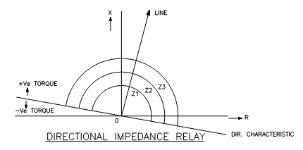
The directional unit of the relay causes separation of the regions of the relay characteristic shown in the figure by a line drawn perpendicular to the line impedance locus. The net result is that tripping will occur only for points that are both within the circles and above the directional unit characteristic.
The Reactance-type Distance Relay:

Reactance relay measures V/I Sin0 (i.e. Z sin 0 - Ã). Whenever the reactance measured by the relay is less than the set value, the relay operates. The operating characteristic on R-X diagram is shown in fig
The resistance component of impedance has no effect on the operation of reactance relay, the relay responds solely to reactance component of impedance. This relay is inherently non-directional. The relay is most suitable to detect earth faults where the effect of arc resistance is appreciable.
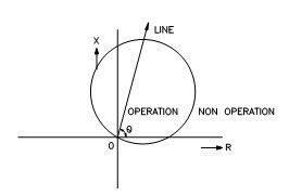
Mho relay:
This is a directional impedance relay, also known as admittance relay. Its characteristic on R-X diagram is a circle whose circumference passes through the origin as illustrated in figure showing that the relay is inherently directional and it only operates for faults in the forward direction.
Modified impedance relay:
Also known as offset Mho relay whose characteristic encloses the origin on R-X diagram as shown in fig

This offset mho relay has three main applications: -
i) Busbar zone backup
ii) Carrier starting unit in distance/carrier blocking schemes.
iii) Power Swing blocking.
Main Features in Distance Scheme
Distance schemes consist of the following major components:-
i) Starters.
ii) Measuring units.
iii) Timers
iv) Auxiliary relay
i) Starters: -
The starting relay (or starter) initiates the distance scheme in the event of a fault within the required reach
(more than zone-3).
Other functions of the starter are: -
a) Starting of timer relays for second and third zones.
b) Starting of measuring elements.
The starters are generally of Mho or impedance type.
With Mho type starters: -
Measuring units for phase and earth faults can be either directional or non-directional as Mho starter is inherently directional
With impedance type starters: -
Measuring units have to be directional as impedance starters are non – directional.
The under impedance relay can be used in conjunction with the directional relay as starter which will then function similar to the Mho starter.
ii) Measuring units: -
They are generally of a mho or reactance or a combination of mho, reactance and resistance types.
Phase Fault Units:-
These measuring units are fed with line to line voltages (such as Vab, Vbc) and difference between line
currents (Ia-Ib). They measure the positive sequence impedance from the relay location to the fault point.
Three such relays respond correctly to all possible single line to ground faults line to line faults, double line to
ground faults and 3-phase faults. They however do not respond correctly to earth faults.
Earth Fault Units:
These measuring units utilize line to neutral voltage (Van, Vbn Vcn) and phase currents (Ia, Ib, Ic). In
order to make these units measure the positive sequence impedance correctly, a zero sequence current
compensation is to be provided which is obtained by:
KN = (Z0-Z1)/ 3*Z1 (where Z1 = positive sequence impedance of line.
Z0 = Zero sequence impedance of line)
In the current circuit (1+KN) Ia will be fed for the above measurement.
iii) Timers:
Timer relays when initiated by starters provide the time lag required for zones. They also will be used for
zone extension purpose whenever required.
iv) Auxiliary relays:
Distance scheme comprises of several auxiliary relays, which perform functions such as flag indications,
trippings, signaling, alarm etc.
Additional Features in distance schemes: -
i) Power Swing blocking relay
ii) VT fuse failure relay.
iii) Switch onto fault relay
iv) Fault locator
v) Auto-reclosing scheme.
vi) Carrier communication scheme.
i) Power Swing blocking: -
Distance relay which respond to balanced 3-phase changes in the impedance will be affected by power swings. These swings or oscillations occur following a system disturbance such as major load change or a dip in voltage due to delayed fault clearance.
In case of fault, the transition from period of impedance locations (25 to 33% of starter impedance) to fault impedance (starter impedance) is sudden whereas during power swings. The PSB relays use this difference to block the tripping during swings.
ii) VT fuse failure relay: -
The distance relays being voltage restraint O/C relays, loss of voltage due to main PT fuse failure or inadvertent removal of fuse in one or more phases will cause the relay operation. The fuse failure relay will sense such condition by the presence of residual voltage without residual current and blocks the relay.
iii) Switch onto fault: -
When the line is switched on to a close by fault (say after line clear with earth switch closed), the voltage at the relaying point will be zero. Faults of this type will normally be cleared by backup zones.
The voltage applied to the relay is low and this condition occurring simultaneously with the operation of starter will cause instantaneous trip by SOTF relay. This SOTF feature will be effective only for about 1-2 seconds after the line is charged. Faults occurring after this time will be measured in the normal way.
iv) Fault locator: -
It measures the distance between the relay location and fault location in terms of Z in Ohms, or length in KM or percentage of line length.
This relay gets same inputs as the distance relay (connected in series with one of the main relays). The measurement is initiated by trip signal from distance relays.
The fault locator gives the exact location of the fault, thereby reducing the time of restoration.
Auto Reclosing Schemes:-
Types of Faults:-
i) Transient Faults:-
These are cleared by the immediate tripping of circuit breakers and do not recur when the line is re-energised.
ii) Semi-permanent Faults:-
These require a time interval to disappear before a line is charged again.
iii) Permanent Faults:-
These are to be located and repaired before the line is re-energised.
About 80-90% of the faults occurring are transient in nature. Hence the automatic reclosure of breaker (after tripping on fault) will result in the line being successfully re-energised, thereby
a) Decreasing outage time
b) Improving reliability
c) Improving system stability
d) Reduces fault damage and maintenance time
Dead Time:-
The time between the Auto-reclosing scheme being energised and the 1st reclosure of the circuit breaker . This is normally set at 1 Sec.
Reclaim Time:-
The time following a successful closing operation measured from the instant the auto-reclosing relay closing contacts making which must elapse before the auto-reclosing relay initiated another reclosing attempt. In other words, it may be said to be the time between 1st and 2nd re-closure.
Types of Auto-reclosing schemes (based on phase):
a) Three phase Auto-reclosing:
This type of auto-reclosing causes an immediate drift apart of the two systems and hence no interchange of synchronizing power can take place during the dead time.
b) Single Phase Auto-reclosing:
In this only the faulty phase (which already has tripped on SLG fault) is reclosed without causing interruption in interchange of synchronising power between two systems through other two healthy phases.
Types of Auto-reclosing schemes (case on attempts of reclosure):
a) Single Shot Auto-reclosing:-
In this scheme, breaker is reclosed only once on a given fault before lockout of circuit breaker occurs. High speed auto-reclosing for EHV system is invariably single shot.
b) Multi-shot Auto-reclosing:-
In this scheme, more than one reclosing attempt is made for a given fault before lockout of the circuit breaker occurs. Repeated closure attempts with high fault level would seriously affect the circuit breaker, equipment and system stability. The factors that must be taken into account:-
i) Circuit Breaker Limitations:-
Ability of circuit breaker to perform several trip close operations in quick succession.
ii) System Conditions:-
In the percentage of the semi-permanent faults (which could be burnt out) is moderate, for example on the lines through the forest, multishot auto-reclosing is followed.
Types of Auto-reclosing (depending on speed):
I) High speed Auto-reclosing:
This aids in fast restoration of supply but should be done by taking into account the following factors:-
i) System disturbance time can be tolerated without loss of system stability
ii) Characteristics of protection schemes and circuit breaker.
II) Low Speed or Delayed Auto-reclosing:-
This is suitable for highly interconnected systems where the loss of a single line is unlikely to cause two sections of the system to drift apart and loose synchronism.
For EHV Systems:-
a) Choice of Dead Time:
Lower limit is decided by deionising time of circuit breaker.
Upper limit is decided by transient stability and synchronism.
Long transmission lines require longer dead time for single phase faults.
The dead time for high speed auto-reclosing scheme with EHV system is 0.3-0.8 Sec.
b) Choice for reclaim time:-
This should not be set to such a low value that the operating cycle of breaker is exceeded
when two fault incident occurs close together. The reclaim time will be in the range of 10-30
Sec., depending on the breaker opening and closing mechanisms.
when two fault incident occurs close together. The reclaim time will be in the range of 10-30
Sec., depending on the breaker opening and closing mechanisms.
Carrier Communication Schemes:-
The main disadvantage of conventional time-stepped distance protection is that the instantaneous Zone-1 of the protective scheme at each end of the protected line is set to cover 80% of the line and hence faults in the balance 20% of the line (at each end) are cleared in Zone-2 time, which is undesirable.
The desirable scheme is the one wherein the relays clear the faults on the 100% of the protected line instantaneously and also provide backup for uncleared faults on adjacent lines. This can be achieved by interconnecting the distance relays are each end of the line by a signaling channel (which can be either pilots, a power line carrier communication channel, a radio link or a microwave channel).
The purpose of the signaling channel is to transmit the information about the system conditions at one end of the protected line to the other end and initiate or prevent tripping of the remote circuit breaker. The former arrangement is referred to as a “Transfer trip scheme” while the latter is known as “Blocking scheme”
a) Transfer trip scheme:-
In this scheme, the distance relay at one end of the protected lines sends a carrier signal to the relay at other end of the line for inter-tripping, thereby clearing the faults on entire line instantaneously.
Transfer trip is of two types:-
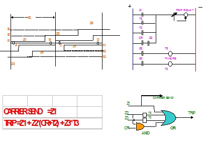
i) Under-reaching scheme:
The scheme in which the Zone-1 relay (set to cover about 80% of ZL) is used to send a signal to the remote end of the feeder for inter-tripping is termed as transfer trip under-reaching scheme. To avoid mal-operation due to receipt of false signal, the receiving end relay operation is inter-locked with its Zone-3/starter operation i.e. the scheme operates either by its own Zone-1 relay operation or by receipt of carried and its Zone-3/starter operation.

ii) Over-reaching scheme:-
This scheme is suitable for short lines where an underreaching Zone-1 would be too short to be of any practical use. In this scheme the relay set to reach beyond 100% of the line, is used to send an inter-tripping signal to the remote end of the line. It is essential that the receive relay contact be monitored by a directional relay to ensure that tripping does not take place unless the fault is within the protected section. The disadvantage of this scheme is that there is no independent Zone-1 tripping. The fast tripping therefore relies entirely on signaling channel.
The disadvantages of these schemes is that the signal is transmitted over the fault line section. Distortion of the signal may occur due to attenuation introduced into the line by the fault.
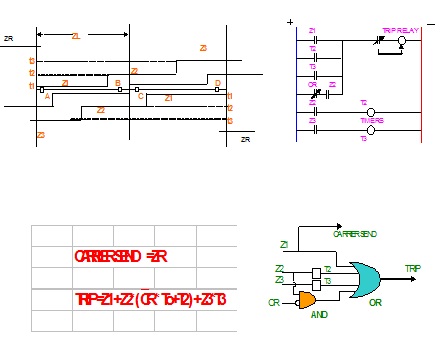
b) Blocking schemes:
In this scheme, a blocking signal is sent by the reverse looking directional unit ZR to prevent instantaneous tripping for Zone-2 & Zone-3 faults, external to the protected line. Here ZR must operate faster then forward looking Zone-3 units and the signaling channel must also be extremely fast is operation.
Though all the distance schemes with carrier inter-tripping/carrier blocking facility are procured, the same are yet to be commissioned.
Factors affecting distance relay operation:-
i) Fault resistance.
ii) Infeed effect.
iii) Branching-off effect.
iv) Load encroachment.
i) Fault resistance:-
Fault resistance has two components:-
a) Arc resistance.
b) Ground resistance.

In a fault between phases, only arc resistance is involved.
For a fault at F, the actual line impedance
= R + JX = ZL
Due to the presence of fault resistance, the impedance measured by the relay
= R + JX + RF = ZR (where ZR > ZL)
Fault arc resistance is given by Warrington
Rarc = 8750 xl / I 1.4
where l = length of arc in ft
I = fault current in Amps
The arc resistance has little effect on accuracy of zone-1 unit as it operates instanteously before the arc can stretch appreciably except in case of short lines. Reactance relays are therefore used for short lines where the fault resistance may be comparable with that of the protected lines and also for ground faults where the ground resistance is high.
The arc resistance will have greater impact on accuracy of backup zones (time delayed) as the arc stretches appreciably.
ii) Infeed effect:-
The effect of intermediate current source between relay location and fault point is termed as infeed effect. Consider the sketch indicated in fig ---

A fault at F on the line BC is at a distance of Z1+Z2 for the relay at station A. But when current I2 flows from bus D, the impedance to the fault as seen by the relay at A is
Z1 + Z2 + Z2 x (I2/I1).
Thus the fault is seen by the relay as farther than what it really is, i.e. distance relay under reaches due to the infeed effect.
The effect of infeed becomes more pronounced with more interconnections at station B.
iii) Branching-off effect:
Consider the sketch indicated in fig ---

A fault at F is at the distance of Z1+Z2 for the relay at station A. But when current I1 gets distributed as I2 & I3 at station B, the impedance to fault seen by the relay at station A will be (Z1 + I3/I1 * Z2) which is less than (Z1+Z2).
Then the fault is seen by the relay as nearer than what it really is i.e. distance relay overreaches due to branching-off effect. This overreaching tendency will cause the relay to loose its selectivity.
iv) Load encroachment:
While protecting long lines the necessary reach may be so large that the minimum service impedance (or load impedance) falls within the region of the starter. This would result in tripping without there being any fault. The two conditions i.e. operation at heavy load and short circuit differ by virtue of phase angle between voltage and current. For the load impedance, the phase angle will be within +30 to -30 Deg. While during short circuits, the fault impedance has a phase angle of 60 to 80 deg. (i.e. line angle).
Load encroachment problem is more pronounced in case of under impedance starters and gets lessened in case of mho, elliptical, lens etc, type of starters. Relays with suitable characteristic on R-X diagram have to be carefully chosen to protect long and heavily loaded lines, and this becomes easily possible with microprocessor based numerical relays.
5 comments:
Great Blog,Thanks for sharing such beautiful information with us. I hope to will share some more information about Arc flash protection levels. Please visit our website Arc flash protection levels
Nice your Blog.bus bar is the one of right system of power distribution .I read your post and i recommend read this post other people.
I am not sure where you're getting your info, but great topic. I needs to spend some time learning more or understanding more. Thanks for magnificent information I was looking for this info for my mission.
Water System Monitoring
We procured SEL 311L line differential relay in which the 850 nm FO communication is available and we procured 1310nm single mode FO cable for communicating between up/down stream relays
Please share your knowledge, the cable is compatible with this relay if not provided alternate arrangement like FO converter Multi mode to single mode converters.
Regs
G. Rajendran
I wanted to thank you for this great read!! I definitely enjoying every little bit of it I have you bookmarked to check out new stuff you post.
Water System Monitoring
Post a Comment