Busbar Arrangements & Protection
In
order to maintain system stability and minimise fault damage due to high fault
levels, instantaneous tripping for busbar faults is necessary.
Busbar
protection scheme should be:
a)
Completely reliable
b)
Absolutely stable for heavy through faults
c)
Selective
d)
Accurate and fast operating
General Busbar Arrangements
a) Single Busbar Arrangement
This has only single busbar to which
all lines/Transformers/Generators, etc. are connected. In the event of the
fault on the bus entire bus has to be deenergised and a major outage occurs.

b) Single Sectionalised Busbar
Scheme
In
this, main bus is divided into two sections with a circuit breaker. One
complete section can be taken out for maintenance or for breakdown works
without distribution continuity of other section.
c)
Main &
transfer busbar scheme: -
With
this arrangement, any line breaker (one at a time) requiring maintenance can be
transferred to transfer bus. The feeder protection thus gets transferred to
trip bus couple breaker. On fault occurrence or maintenance, entire bus becomes
de-energised.
d)
Double Bus arrangement: -
Flexibility of
transferring any line to any of the buses. On fault occurrence or maintenance
only one bus becomes dead, while other bus remains in service.

e)
Double bus and transfer bus arrangement:-
Combination of main
and transfer bus and double bus arrangement.

f) Double bus and bypass isolator arrangement:

g) Double break bus system:

h) Breaker and half arrangement: - (One and half Breaker arrangement)

Advantages:-
1)
It has 3 breakers for two connections.Each circuit is
connected to a particular bus.
2)
No changeover of line from one bus to the other is
required.
3)
This pairing is done such that one is a source and the
other a load.
4)
For breaker maintenance of any line, the load gets
transferred to the other bus.
5)
On occurrence of a bus fault or for maintenance all the
interconnections will be on healthy bus.
6)
Even if both
buses become dead, lines can still be in service through the tiebreakers.
Busbar Protection
Scheme
1) High
impedance circulating current scheme
2) Biased
differential or low impedance circulating scheme.
|
S.No.
|
Details
|
High impedance circulating current relay
|
Low impedance biased differential relay
|
|
1.
|
Principle
|
The currents entering and leaving the busbar are compared
continuously. It involves choosing of impedance high enough to stabilise the
relay for heavy external faults.
|
It has differential and bias setting. The resultant bias
is proportional to arithmetic sum of all currents, whereas the operating
current is vector sum of all circuit currents.
|
|
2.
|
CTs
|
It requires all identical CT ratios
|
It can work with
CTs of unequal ratios also.
|
|
3.
|
Burden
|
Imposes comparatively high burden on CTs. Auxiliary CTs
reduce the performance of scheme
|
Imposes less burden on CTs. Auxiliary CTs have no effect
on performance of scheme
|
|
4.
|
CT Saturation
|
Operation of scheme even when CTs get saturated during
internal faults
|
Operation of scheme
even when CTs get saturated during internal faults.
|
|
5.
|
Performance
|
Highly sensitive for internal faults and completely stable
for external faults
|
Highly sensitive for internal faults and completely for
external faults
|
High Impedance Busbar Protection:-
Relay Operating Current and Stabilising Resistor are to be
set in high impedance scheme. An
Operating Current (Iop) of 10% or 20% of In can be set.
During through fault, the voltage developed across the relay
is
V = If
(RCT + 2 RL)
Where If = Fault current
RCT = Internal resistance of CT
RL = Cable resistance
Stabilising Resistor Rst can be computed as follows.
Rst =
--- (-) ----------------------
Iop Iop**2
For some high impedance schemes,
only Voltage Setting ‘V’ will be set.(The calculations are similar to that of Restricted Earth Fault relay setting for the
Transformer protection).
Low Impedance Busbar Scheme:-
This relay operates on
circulating current principle and differential current setting ( 20% In) is adopted on the relay. The bias setting is generally set by the
relay manufacturer based on bus fault levels.
Busbar Protection
a) Check Feature: -
To prevent incorrect tripping due to
damage to wiring and equipment from extraneous sources, check relay is
provided. This check relay is provided by duplication of primary protection
using a second set of current transformers cores on all circuits other than bus
section and bus couple units. The check system is arranged in a similar manner
of the primary protection, but forms one zone only covering the whole of the
busbars (in case of single sectionalized busbar or both the buses (in case of
double busbar arrangement).
b) Supervision
When a CT secondary winding or
connections between CT and the relay circuit become open circuited, the relay
may maloperate for load or through faults depending on the effective primary
setting. This condition of an open circuit can be detected by using supervision
(over voltage) relay, which is arranged to give alarm.
The
supervision must be time delayed to avoid a false alarm during genuine fault
conditions, typically three seconds is adopted.

BREAKER FAILURE RELAY (LBB PROTECTION)
Main
protective schemes provided for line /transformer/generator are required to
operate and clear the fault immediately, isolating the faulty section of the
system. It is then important that the circuit breaker operates correctly,
clearing the fault quickly by tripping. However there is a risk that breaker
may not trip (either due to mechanical sluggishness or due to inability to
interrupt heavy fault current). Then the fault gets cleared by backup relays at
remote stations.
Increasing
power system complexity demands shorter fault clearing times. It is therefore
necessary to provide breaker failure relay (also called “Local breaker backup
relay” or “Stuck breaker protection”). This scheme will isolate the bus to
which the stuck breaker is connected, faster. It comprises of O/L & E/L
relays with a timer. The LBB relay is energised by trip command of main
protection schemes and thus initiate master trip relay of the busbar protection
scheme after elapsing of defined time. Then the entire breaker connected to the
bus get tripped, thus isolating faulty element.
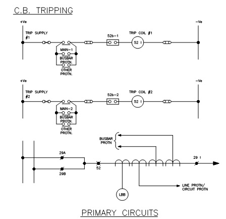
Even
if the busbar protection scheme is not available, the LBB scheme can be made
use of by providing special trip circuits and trip relays similar to that of
bus protection trip circuits for each line. A schematic for such application is
indicated in figure.
No comments:
Post a Comment