
Why Capacitive
Voltage Transformer?
•
At
high system voltages the cost of conventional potential transformer is high,
due to prohibitive cost of insulation.
•
It
is possible to obtain voltage from capacitor divider as the insulation is
inherent in its design at no extra cost.
•
Further
economy can be obtained by using capacitor divider as a coupling capacitor for
Power Line Carrier Communication.
•
The
CVT has the following inherent advantages :
•
Since
the primary insulation is made up of capacitors elements connected in series, the surge withstand
capability of a CVT is very good. It acts a surge suppressor.
•
The
Ferroresonance is controllable in a CVT because the same happens between the
capacitor part and the electromagnetic unit of the CVT which are known values.
•
Since
it is packed and shipped in parts, handling ,
erection and assembly of the same at site is convenient.

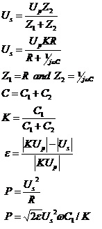
Assuming the intermediate potential
transformer is absent
Expression for Us
•
The
per unit error is
Considering
On simplifying
•
This
leads to the conclusion that for given error the power output is proportional
to
–
Secondary
output voltage Us
–
Upper
stack capacitance C1
•
As
the output voltage Us is usually constant, very large capacitance (C1)
is required to get sufficient power output
•
This
is economically unacceptable.
•
Two
modifications required to improve the situation
–
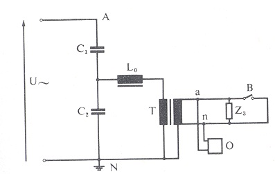
Introduction
of an intermediate stepped potential transformer to boost Us. It can be 20 kV primary, the burden is
connected at its secondary at
Volts
–
Elimination
of the main source of phase angle error due to the capacitance C(=C1+C2
) by a series inductance tuned to resonate with C at the power frequency
•
L is variable inductive choke used for phase angle error correction.
•
It
is tuned to resonate with C (=C1+C2) at nominal power
frequency.
•
Wound
PT is used to increase the available output power, for a given maximum error
limit and C1

• Leq
is the sum of choke inductance and leakage inductance of the wound PT
• Magnetizing inductance of the PT is neglected

•
It
can be seen that the choice of a suitable value of L tends to reduce the phase
angle error.
•
As the value of L increases U decreases until it
is in phase with V and then increases.
•
If the burden is short circuited a considerable
over-voltage appears across C2, due to resonance of L and C.

Steady State
Performance
CVT Accuracy -
Concept of Simultaneous burden on CVTs
•
In
case of CVTs and PTs, all the secondary windings are wound on a common
secondary core.
•
Hence,
the load connected on any winding, affects the accuracy of the other.
•
The
requirement of the standard is that the accuracy should be guaranteed for the
total connected burden on all windings put together. For the total burden, the burden of open
delta windings may not be considered as they are not continuous loads.
•
Whenever
we are unable to meet the accuracy with the total combined load, we specify the
maximum simultaneous burden upto which the accuracy of the metering class is
guaranteed.
Transient Performance
•
Transient
performance is the response of secondary of a CVT in relation to transient
(sudden) changes in primary voltages.
•
Since
high speed protective relays operate usually within one cycle, it is essential
that a CVT should have good transient response, i.e. it should reach its steady
state value within 10 milliseconds after a step change in the input.
•
Various
situations causing transients in CVT are
•
Energizing
and de-energizing of the line
•
Short
circuit on the primary terminals
•
Rapid
reclosure within a few seconds
•
Releasing
of a secondary short circuit
•
Ferro-resonance
•
Various
situations causing transients in CVT are
•
Energizing
and de-energizing of the line
•
Short
circuit on the primary terminals
•
Rapid
reclosure within a few seconds
•
Releasing
of a secondary short circuit
•
Ferro-resonance

•
The
transients produce non power frequency superimposed oscillations on the
secondary side.
•
The
transient oscillations can be damped rapidly by using suitable damping device
like ferroresonance protection circuit.
Ferroresonance
•
A
practical CVT consists of tuning inductance and wound PT each having iron core,
and capacitance. Whenever a capacitor and non-linear inductor are
connected in series, there is a danger
of non-linear energy interchanges at sub-harmonic frequencies
•
This
causes large overvoltage in the circuit
•
To
avoid ferroresonance the operating flux of iron parts is kept at 1/2 to 1/3rd
of the saturation flux density.
•
Alternately
a special provision for damping the oscillations is provided.
PLCC

1.
Circuit
breaker
2.
Wave
Trap
3.
High-voltage
line
4.
Grounding
switch
5.
Impedances
of the sub-station against ground
6.
Coupling
capacitor
7.
Line
matching unit
8.
Grounding
switch
9.
Drain
coil
10. Lightning arrestor
11. Connection for the h.f.cable to the
carrier set
Type Tests
Accuracy Test
•
Involves
measurement of accuracy in limits of frequency and temperature.
•
Normally
we carry out the tests only in limits of frequency because of non availability
of a temperature controlled chamber. If demanded by the customer, we submit
calculations for the same.
•
The
temperature characteristics of the capacitor divider are measured by conducting
the measurements on a small model capacitor stack.
•
For
metering core, the frequency range is 49.5 to 50.5 Hz.
•
For
protection core, the frequency range is 48 to 51 Hz. or 48.5 Hz to 51.5 Hz.
Ferro-resonance Test
•
Checks
the capability of the CVT to suppress high voltages and harmonics created due
to ferro-resonance.
•
Simulated
by short circuiting the secondary for 100 milliseconds in a charged CVT.
The voltage should
return back to normal within 10 cycles
Transient Response
Test
•
Since
a CVT is a tuned device, the response of the secondary for any change on the
primary is checked by this test.
•
A
primary short circuit is created and the time taken by the secondary to respond
is measured.
•
The
secondary voltage should collapse to less than 10% of its value before short
circuit within 1 cycle i.e 20 ms
High Frequency Test
•
These
are required to check the compliance of the CVT for PLCC application.
•
These
consist of measuring
- High Frequency capacitance and Equivalent Series Resistance
- Stray Capacitance and Stray Conductance
- High Frequency capacitance and Equivalent Series Resistance
- Stray Capacitance and Stray Conductance
•
The
normal frequency of operation for PLCC is between 40 to 500 KHz.
Temperature Rise Test
on the EMU
•
To
check its capability to take the guaranteed thermal burden continuously
Short Circuit Test
•
Same
as ferro-resonance, but for the fact that the secondary is shorted for at least
1 second
No comments:
Post a Comment